draw 3d shapes usings vertices and tris opengl
Section three.i
Shapes and Colors in OpenGL 1.i
This section introduces some of the cadre features of OpenGL. Much of the discussion in this section is limited to 2D. For now, all you lot need to know about 3D is that it adds a third management to the x and y directions that are used in 2nd. By convention, the third management is calledz. In the default coordinate arrangement, the x and y axes prevarication in the airplane of the image, and the positive direction of the z-axis points in a direction perpendicular to the paradigm.
In the default coordinate organisation for OpenGL, the image shows a region of 3D infinite in which ten, y, and z all range from minus one to 1. To show a different region, you lot have to apply a transform. For now, nosotros will just use coordinates that lie between -one and 1.
A notation nearly programming: OpenGL can be implemented in many unlike programming languages, but the API specification more or less assumes that the language is C. (See Section A.2 for a curt introduction to C.) For the almost role, the C specification translates directly into other languages. The principal differences are due to the special characteristics of arrays in the C language. My examples will follow the C syntax, with a few notes nearly how things tin can exist dissimilar in other languages. Since I'm following the C API, I will refer to "functions" rather than "subroutines" or "methods." Section 3.six explains in detail how to write OpenGL programs in C and in Java. Yous will need to consult that department before you can do whatever actual programming. The live OpenGL 1.ane demos for this book are written using a JavaScript simulator that implements a subset of OpenGL 1.ane. That simulator is discussed in Subsection 3.vi.three.
iii.1.ane OpenGL Primitives
OpenGL tin depict only a few basic shapes, including points, lines, and triangles. In that location is no congenital-in support for curves or curved surfaces; they must be approximated by simpler shapes. The basic shapes are referred to equally primitives. A archaic in OpenGL is defined by its vertices. A vertex is but a indicate in 3D, given past its x, y, and z coordinates. Let's jump right in and see how to draw a triangle. It takes a few steps:
glBegin(GL_TRIANGLES); glVertex2f( -0.7, -0.v ); glVertex2f( 0.7, -0.5 ); glVertex2f( 0, 0.7 ); glEnd();
Each vertex of the triangle is specified by a phone call to the part glVertex2f. Vertices must exist specified betwixt calls to glBegin and glEnd. The parameter to glBegin tells which type of primitive is being drawn. The GL_TRIANGLES primitive allows yous to draw more than one triangle: Only specify three vertices for each triangle that you want to draw. Note that using glBegin/glEnd is non the preferred fashion to specify primitives, even in OpenGL 1.1. Nonetheless, the alternative, which is covered in Subsection iii.4.2, is more complicated to utilise. You should consider glBegin/glEnd to be a user-friendly way to learn about vertices and their backdrop, but not the way that you will actually do things in modernistic graphics APIs.
(I should annotation that OpenGL functions actually just ship commands to the GPU. OpenGL tin can salve upwards batches of commands to transmit together, and the drawing won't actually be done until the commands are transmitted. To ensure that that happens, the function glFlush() must be chosen. In some cases, this part might exist called automatically by an OpenGL API, but you might well run into times when you lot have to telephone call it yourself.)
For OpenGL, vertices accept three coordinates. The function glVertex2f specifies the x and y coordinates of the vertex, and the z coordinate is set to zero. There is also a part glVertex3f that specifies all three coordinates. The "2" or "3" in the proper noun tells how many parameters are passed to the function. The "f" at the end of the name indicates that the parameters are of type float. In fact, there are other "glVertex" functions, including versions that accept parameters of blazon int or double, with named like glVertex2i and glVertex3d. There are even versions that take four parameters, although it won't be clear for a while why they should exist. And, as we will see later, in that location are versions that have an assortment of numbers instead of individual numbers equally parameters. The entire fix of vertex functions is often referred to equally "glVertex*", with the "*" standing in for the parameter specification. (The proliferation of names is due to the fact that the C programming language doesn't support overloading of role names; that is, C distinguishes functions only by their names and not past the number and type of parameters that are passed to the office.)
OpenGL i.1 has ten kinds of primitive. 7 of them yet be in modern OpenGL; the other three take been dropped. The simplest archaic is GL_POINTS, which only renders a point at each vertex of the archaic. By default, a point is rendered as a single pixel. The size of point primitives can be changed by calling
glPointSize(size);
where the parameter, size, is of type float and specifies the diameter of the rendered point, in pixels. By default, points are squares. You can get round points by calling
glEnable(GL_POINT_SMOOTH);
The functions glPointSize and glEnable change the OpenGL "land." The state includes all the settings that touch rendering. We will run across many state-irresolute functions. The functions glEnable and glDisable can exist used to turn many features on and off. In general, the rule is that whatever rendering characteristic that requires extra ciphering is turned off by default. If you want that feature, you have to turn it on by calling glEnable with the appropriate parameter.
There are 3 primitives for cartoon line segments: GL_LINES, GL_LINE_STRIP, and GL_LINE_LOOP. GL_LINES draws disconnected line segments; specify two vertices for each segment that you want to draw. The other ii primitives depict connected sequences of line segments. The just difference is that GL_LINE_LOOP adds an extra line segment from the terminal vertex dorsum to the kickoff vertex. Here is what you lot get if use the same 6 vertices with the four primitives we take seen so far:
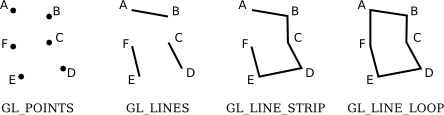
The points A, B, C, D, E, and F were specified in that order. In this illustration, all the points lie in the same plane, but go along in mind that in full general, points tin can be anywhere in 3D infinite.
The width for line primitives tin can be set past calling glLineWidth(width). The line width is e'er specified in pixels. It is non subject to scaling by transformations.
Let'due south look at an instance. OpenGL does not have a circle primitive, merely we can approximate a circle by drawing a polygon with a big number of sides. To depict an outline of the polygon, we can use a GL_LINE_LOOP primitive:
glBegin( GL_LINE_LOOP ); for (i = 0; i < 64; i++) { bending = 6.2832 * i / 64; // vi.2832 represents 2*PI 10 = 0.5 * cos(angle); y = 0.5 * sin(bending); glVertex2f( x, y ); } glEnd(); This draws an approximation for the circumference of a circle of radius 0.5 with center at (0,0). Call up that to learn how to apply examples similar this one in a complete, running program, you will have to read Department iii.6. Likewise, you might take to make some changes to the code, depending on which OpenGL implementation you are using.
The next prepare of primitives is for cartoon triangles. In that location are three of them: GL_TRIANGLES, GL_TRIANGLE_STRIP, and GL_TRIANGLE_FAN.
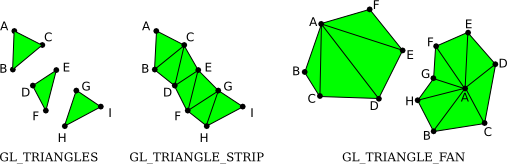
The three triangles on the left brand up i GL_TRIANGLES primitive, with ix vertices. With that primitive, every set of three vertices makes a separate triangle. For a GL_TRIANGLE_STRIP archaic, the first three vertices produce a triangle. After that, every new vertex adds some other triangle to the strip, connecting the new vertex to the two previous vertices. Two GL_TRIANGLE_FAN primitives are shown on the correct. Again for a GL_TRIANGLE_FAN, the first three vertices make a triangle, and every vertex afterward that adds anther triangle, just in this case, the new triangle is made by connecting the new vertex to the previous vertex and to the very first vertex that was specified (vertex "A" in the pic). Note that Gl_TRIANGLE_FAN can exist used for cartoon filled-in polygons. In this moving-picture show, by the way, the dots and lines are not office of the primitive; OpenGL would only draw the filled-in, green interiors of the figures.
The iii remaining primitives, which have been removed from modern OpenGL, are GL_QUADS, GL_QUAD_STRIP, and GL_POLYGON. The proper noun "quad" is short for quadrilateral, that is, a four-sided polygon. A quad is determined by four vertices. In social club for a quad to be rendered correctly in OpenGL, all vertices of the quad must lie in the aforementioned plane. The same is true for polygon primitives. Similarly, to be rendered correctly, quads and polygons must be convex (see Subsection 2.2.iii). Since OpenGL doesn't cheque whether these weather are satisfied, the use of quads and polygons is error-prone. Since the same shapes can easily exist produced with the triangle primitives, they are not really necessary, but here for the tape are some examples:
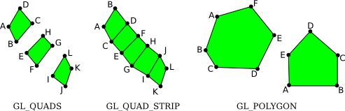
The vertices for these primitives are specified in the order A, B, C, .... Notation how the order differs for the two quad primitives: For GL_QUADS, the vertices for each individual quad should exist specified in counterclockwise lodge around the quad; for GL_QUAD_STRIP, the vertices should alternate from one side of the strip to the other.
3.1.2 OpenGL Colour
OpenGL has a large collection of functions that can exist used to specify colors for the geometry that nosotros draw. These functions have names of the form glColor*, where the "*" stands for a suffix that gives the number and blazon of the parameters. I should warn y'all now that for realistic 3D graphics, OpenGL has a more complicated notion of color that uses a different set of functions. Yous will larn about that in the next chapter, merely for now nosotros volition stick to glColor*.
For instance, the function glColor3f has three parameters of type float. The parameters requite the red, green, and bluish components of the colour equally numbers in the range 0.0 to 1.0. (In fact, values outside this range are allowed, even negative values. When color values are used in computations, out-of-range values will be used equally given. When a color actually appears on the screen, its component values are clamped to the range 0 to 1. That is, values less than zero are changed to zero, and values greater than ane are changed to 1.)
You tin can add a fourth component to the color by using glColor4f(). The fourth component, known as alpha, is non used in the default cartoon mode, merely it is possible to configure OpenGL to apply it as the degree of transparency of the color, similarly to the employ of the alpha component in the 2d graphics APIs that nosotros take looked at. You need two commands to plow on transparency:
glEnable(GL_BLEND); glBlendFunc(GL_SRC_ALPHA, GL_ONE_MINUS_SRC_ALPHA);
The starting time command enables use of the alpha component. It can be disabled by calling glDisable(GL_BLEND). When the GL_BLEND selection is disabled, alpha is but ignored. The second command tells how the alpha component of a color will exist used. The parameters shown hither are the most mutual; they implement transparency in the usual way. I should note that while transparency works fine in 2D, it is much more difficult to use transparency correctly in 3D.
If yous would like to employ integer color values in the range 0 to 255, you can use glColor3ub() or glColor4ub to set the color. In these role names, "ub" stands for "unsigned byte." Unsigned byte is an viii-bit data blazon with values in the range 0 to 255. Hither are some examples of commands for setting drawing colors in OpenGL:
glColor3f(0,0,0); // Draw in blackness. glColor3f(1,ane,i); // Draw in white. glColor3f(1,0,0); // Depict in total-intensity red. glColor3ub(1,0,0); // Draw in a color merely a tiny fleck different from // black. (The suffix, "ub" or "f", is important!) glColor3ub(255,0,0); // Depict in full-intensity red. glColor4f(ane, 0, 0, 0.5); // Depict in transparent cerise, merely only if OpenGL // has been configured to do transparency. By // default this is the same as cartoon in plain scarlet.
Using any of these functions sets the value of a "current color," which is part of the OpenGL state. When you generate a vertex with one of the glVertex* functions, the current color is saved along with the vertex coordinates, every bit an attribute of the vertex. We will see that vertices can take other kinds of aspect besides equally colour. One interesting bespeak virtually OpenGL is that colors are associated with individual vertices, not with complete shapes. By irresolute the current color betwixt calls to glBegin() and glEnd(), y'all tin can become a shape in which dissimilar vertices accept different colour attributes. When you do this, OpenGL will compute the colors of pixels within the shape by interpolating the colors of the vertices. (Again, since OpenGL is extremely configurable, I have to note that interpolation of colors is just the default behavior.) For example, here is a triangle in which the three vertices are assigned the colors cherry-red, light-green, and bluish:
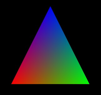
This image is often used as a kind of "Hello World" example for OpenGL. The triangle can be fatigued with the commands
glBegin(GL_TRIANGLES); glColor3f( 1, 0, 0 ); // scarlet glVertex2f( -0.8, -0.8 ); glColor3f( 0, 1, 0 ); // green glVertex2f( 0.viii, -0.viii ); glColor3f( 0, 0, 1 ); // blue glVertex2f( 0, 0.9 ); glEnd();
Note that when drawing a primitive, you do not need to explicitly set a color for each vertex, as was done here. If yous want a shape that is all 1 color, you simply have to set the current color once, earlier drawing the shape (or just after the call to glBegin(). For example, we can draw a solid yellow triangle with
glColor3ub(255,255,0); // yellow glBegin(GL_TRIANGLES); glVertex2f( -0.5, -0.five ); glVertex2f( 0.5, -0.5 ); glVertex2f( 0, 0.5 ); glEnd();
Also recollect that the color for a vertex is specified before the phone call to glVertex* that generates the vertex.
Here is an interactive demo that draws the basic OpenGL triangle, with different colored vertices. You can control the colors of the vertices to see how the interpolated colors in the interior of the triangle are affected. This is our showtime OpenGL case. The demo actually uses WebGL, then you can use information technology as a test to check whether your spider web browser supports WebGL.
The sample program jogl/FirstTriangle.java draws the basic OpenGL triangle using Java. The plan overabundance/get-go-triangle.c does the same using the C programming language. And glsim/get-go-triangle.html is a version that uses my JavaScript simulator, which implements just the parts of OpenGL 1.i that are covered in this book. Any of those programs could be used to experiment with 2D drawing in OpenGL. And you tin use them to exam your OpenGL programming environment.
A common performance is to clear the drawing surface area by filling it with some groundwork color. It is be possible to do that by drawing a big colored rectangle, but OpenGL has a potentially more efficient mode to do information technology. The function
glClearColor(r,g,b,a);
sets up a color to be used for immigration the drawing area. (This only sets the color; the color isn't used until you actually requite the control to clear the cartoon area.) The parameters are floating bespeak values in the range 0 to 1. At that place are no variants of this function; you must provide all four color components, and they must be in the range 0 to 1. The default clear color is all zeros, that is, blackness with an alpha component also equal to nix. The control to do the bodily clearing is:
glClear( GL_COLOR_BUFFER_BIT );
The right term for what I have been calling the drawing expanse is the color buffer, where "buffer" is a general term referring to a region in retentiveness. OpenGL uses several buffers in improver to the color buffer. Nosotros will encounter the "depth buffer" in merely a moment. The glClear command can be used to clear several dissimilar buffers at the same time, which tin be more efficient than clearing them separately since the immigration tin can be washed in parallel. The parameter to glClear tells information technology which buffer or buffers to clear. To clear several buffers at once, combine the constants that represent them with an arithmetic OR operation. For example,
glClear( GL_COLOR_BUFFER_BIT | GL_DEPTH_BUFFER_BIT );
This is the course of glClear that is generally used in 3D graphics, where the depth buffer plays an essential office. For 2D graphics, the depth buffer is generally non used, and the advisable parameter for glClear is just GL_COLOR_BUFFER_BIT.
3.1.3 glColor and glVertex with Arrays
Nosotros have see that there are versions of glColor* and glVertex* that have different numbers and types of parameters. There are too versions that permit you place all the data for the command in a single array parameter. The names for such versions end with "five". For example: glColor3fv, glVertex2iv, glColor4ubv, and glVertex3dv. The "v" really stands for "vector," meaning substantially a i-dimensional array of numbers. For example, in the function call glVertex3fv(coords), coords would be an array containing at least 3 floating point numbers.
The existence of assortment parameters in OpenGL forces some differences between OpenGL implementations in different programming languages. Arrays in Java are dissimilar from arrays in C, and arrays in JavaScript are different from both. Let'due south look at the situation in C first, since that'due south the language of the original OpenGL API.
In C, assortment variables are a sort of variation on pointer variables, and arrays and pointers tin can be used interchangeably in many circumstances. In fact, in the C API, array parameters are actually specified as pointers. For case, the parameter for glVertex3fv is of type "pointer to float." The actual parameter in a call to glVertex3fv tin can exist an array variable, just it can likewise be any pointer that points to the beginning of a sequence of three floats. Equally an case, suppose that we want to draw a square. We need two coordinates for each vertex of the square. In C, nosotros can put all viii coordinates into 1 array and use glVertex2fv to pull out the coordinates that we need:
float coords[] = { -0.5, -0.5, 0.v, -0.five, 0.v, 0.five, -0.5, 0.5 }; glBegin(GL_TRIANGLE_FAN); glVertex2fv(coords); // Uses coords[0] and coords[ane]. glVertex2fv(coords + two); // Uses coords[two] and coords[3]. glVertex2fv(coords + 4); // Uses coords[4] and coords[5]. glVertex2fv(coords + 6); // Uses coords[half-dozen] and coords[7]. glEnd(); This instance uses "pointer arithmetic," in which coords + Due north represents a arrow to the N-th chemical element of the array. An alternative note would be &coords[North], where "&" is the accost operator, and &coords[North] ways "a pointer to coords[N]". This will all seem very alien to people who are only familiar with Java or JavaScript. In my examples, I will avert using pointer arithmetics, but I will occasionally utilize accost operators.
Equally for Java, the people who designed JOGL wanted to preserve the ability to pull information out of the middle of an array. Notwithstanding, information technology's not possible to work with pointers in Coffee. The solution was to replace a pointer parameter in the C API with a pair of parameters in the JOGL API—one parameter to specify the array that contains the information and i to specify the starting index of the data in the array. For example, hither is how the square-drawing lawmaking translates into Java:
bladder[] coords = { -0.5F, -0.5F, 0.5F, -0.5F, 0.5F, 0.5F, -0.5F, 0.5F }; gl2.glBegin(GL2.GL_TRIANGLES); gl2.glVertex2fv(coords, 0); // Uses coords[0] and coords[1]. gl2.glVertex2fv(coords, 2); // Uses coords[two] and coords[iii]. gl2.glVertex2fv(coords, four); // Uses coords[4] and coords[v]. gl2.glVertex2fv(coords, vi); // Uses coords[6] and coords[7]. gl2.glEnd(); In that location is actually non much difference in the parameters, although the zip in the commencement glVertex2fv is a niggling annoying. The chief divergence is the prefixes "gl2" and "GL2", which are required by the object-oriented nature of the JOGL API. I won't say more almost JOGL here, but if you need to translate my examples into JOGL, y'all should keep in listen the extra parameter that is required when working with arrays.
For the tape, here are the glVertex* and glColor* functions that I will apply in this book. This is non the complete set that is bachelor in OpenGL:
glVertex2f( x, y ); glVertex2fv( xyArray ); glVertex2d( ten, y ); glVertex2dv( xyArray ); glVertex2i( x, y ); glVertex2iv( xyArray ); glVertex3f( 10, y, z ); glVertex3fv( xyzArray ); glVertex3d( x, y, z ); glVertex3dv( xyzArray ); glVertex3i( x, y, z ); glVertex3iv( xyzArray ); glColor3f( r, chiliad, b ); glColor3f( rgbArray ); glColor3d( r, g, b ); glColor3d( rgbArray ); glColor3ub( r, one thousand, b ); glColor3ub( rgbArray ); glColor4f( r, 1000, b, a); glColor4f( rgbaArray ); glColor4d( r, g, b, a); glColor4d( rgbaArray ); glColor4ub( r, g, b, a); glColor4ub( rgbaArray );
For glColor*, continue in listen that the "ub" variations require integers in the range 0 to 255, while the "f" and "d" variations require floating-point numbers in the range 0.0 to 1.0.
3.1.iv The Depth Test
An obvious point almost viewing in 3D is that one object can be backside another object. When this happens, the back object is hidden from the viewer by the front end object. When we create an image of a 3D globe, nosotros have to make sure that objects that are supposed to exist hidden behind other objects are in fact not visible in the epitome. This is the hidden surface problem.
The solution might seem simple enough: Just depict the objects in gild from back to front. If ane object is behind some other, the back object will be covered up later on when the front end object is drawn. This is called the painter'due south algorithm. It'southward essentially what you are used to doing in 2D. Unfortunately, information technology'south not and then easy to implement. Commencement of all, you tin have objects that intersect, so that part of each object is hidden by the other. Whatever club you lot draw the objects in, in that location will be some points where the wrong object is visible. To fix this, you would have to cutting the objects into pieces, along the intersection, and treat the pieces as separate objects. In fact, there can be bug fifty-fifty if in that location are no intersecting objects: It'southward possible to take iii not-intersecting objects where the first object hides role of the second, the 2d hides part of the tertiary, and the third hides part of the first. The painter's algorithm will fail regardless of the order in which the iii objects are fatigued. The solution once again is to cutting the objects into pieces, but now it'southward non and so obvious where to cut.
Even though these problems can be solved, there is some other effect. The right drawing club can change when the point of view is inverse or when a geometric transformation is practical, which means that the correct drawing order has to be recomputed every time that happens. In an animation, that would mean for every frame.
So, OpenGL does not use the painter's algorithm. Instead, it uses a technique called the depth test. The depth test solves the subconscious surface trouble no thing what order the objects are drawn in, so you can draw them in whatsoever society you want! The term "depth" here has to practice with the altitude from the viewer to the object. Objects at greater depth are farther from the viewer. An object with smaller depth will hide an object with greater depth. To implement the depth examination algorithm, OpenGL stores a depth value for each pixel in the image. The extra retentivity that is used to store these depth values makes upwards the depth buffer that I mentioned earlier. During the cartoon process, the depth buffer is used to keep track of what is currently visible at each pixel. When a 2d object is fatigued at that pixel, the information in the depth buffer can exist used to determine whether the new object is in front of or behind the object that is currently visible at that place. If the new object is in front, then the colour of the pixel is changed to show the new object, and the depth buffer is too updated. If the new object is backside the current object, so the data for the new object is discarded and the colour and depth buffers are left unchanged.
By default, the depth examination is not turned on, which can lead to very bad results when cartoon in 3D. Yous can enable the depth test by calling
glEnable( GL_DEPTH_TEST );
It can exist turned off past calling glDisable(GL_DEPTH_TEST). If you lot forget to enable the depth examination when drawing in 3D, the epitome that you get will likely be confusing and volition make no sense physically. You lot can likewise get quite a mess if yous forget to articulate the depth buffer, using the glClear command shown before in this department, at the same time that you lot clear the color buffer.
Here is a demo that lets you experiment with the depth test. It too lets yous see what happens when part of your geometry extends outside the visible range of z-values.
Hither are are a few details about the implementation of the depth test: For each pixel, the depth buffer stores a representation of the altitude from the viewer to the point that is currently visible at that pixel. This value is essentially the z-coordinate of the point, later on any transformations have been applied. (In fact, the depth buffer is frequently called the "z-buffer".) The range of possible z-coordinates is scaled to the range 0 to 1. The fact that there is but a limited range of depth buffer values means that OpenGL can only display objects in a limited range of distances from the viewer. A depth value of 0 corresponds to the minimal altitude; a depth value of 1 corresponds to the maximal distance. When you lot articulate the depth buffer, every depth value is set to one, which can be thought of as representing the groundwork of the image.
You get to choose the range of z-values that is visible in the image, by the transformations that you employ. The default range, in the absence of any transformations, is -1 to ane. Points with z-values exterior the range are non visible in the image. It is a common problem to use too small a range of z-values, so that objects are missing from the scene, or have their fronts or backs cut off, considering they lie exterior of the visible range. You lot might exist tempted to utilize a huge range, to make sure that the objects that you lot desire to include in the image are included inside the range. Even so, that's not a good idea: The depth buffer has a limited number of bits per pixel and therefore a express amount of accurateness. The larger the range of values that it must represent, the harder it is to distinguish between objects that are almost at the same depth. (Recall nearly what would happen if all objects in your scene accept depth values between 0.499999 and 0.500001—the depth buffer might see them all as existence at exactly the same depth!)
There is another issue with the depth buffer algorithm. It can give some strange results when two objects have exactly the same depth value. Logically, it's not even clear which object should be visible, but the existent problem with the depth test is that it might show one object at some points and the second object at another points. This is possible because numerical calculations are non perfectly authentic. Here an actual case:
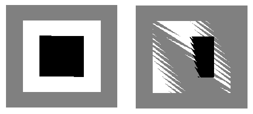
In the two pictures shown here, a gray square was drawn, followed past a white foursquare, followed past a black foursquare. The squares all lie in the same plane. A very small rotation was applied, to force the calculator do some calculations before drawing the objects. The picture on the left was drawn with the depth test disabled, then that, for example, when a pixel of the white square was fatigued, the computer didn't effort to figure out whether information technology lies in front of or behind the gray square; it simply colored the pixel white. On the right, the depth test was enabled, and you tin can see the foreign result.
Finally, by the fashion, note that the discussion here assumes that there are no transparent objects. Unfortunately, the depth test does not handle transparency correctly, since transparency means that two or more objects can contribute to the color of the pixel, only the depth test assumes that the pixel color is the colour of the object nearest to the viewer at that indicate. To handle 3D transparency correctly in OpenGL, you pretty much accept to resort to implementing the painter's algorithm by hand, at least for the transparent objects in the scene.
Source: https://math.hws.edu/graphicsbook/c3/s1.html
0 Response to "draw 3d shapes usings vertices and tris opengl"
Postar um comentário